Finite Element Analysis
repository
Finite Element Analysis involves dividing the physical product into small, ‘finite’ elements and analyzing how these elements interact under various loads and conditions. They are a collection of Partial Differential Equations hence we can perform FEM by hand if we compartmentalize enough. But I am not spending months for my results; so here I am, writing a piece about how I utilized FEM softwares to analyze my model.
The mesh files and formatted calculations can be found on my Github page. The tools I used, all of which are Open Source, are:
- FreeCad(Calculix)
- to construct the model using booleans on primitive solids and to run preliminary calculations (does not support heteregenous models)
- Meshlab/GMESH (
netgen)- for stl to mesh/imp conversion and refining the mesh resolution.
- PreProMax(Calculix)
- post-porocessing software to conduct the main calculations with proper constraints
- ParaView
- powerful visualization software that renders the result from PrePoMax
The specs for our environment is given below:
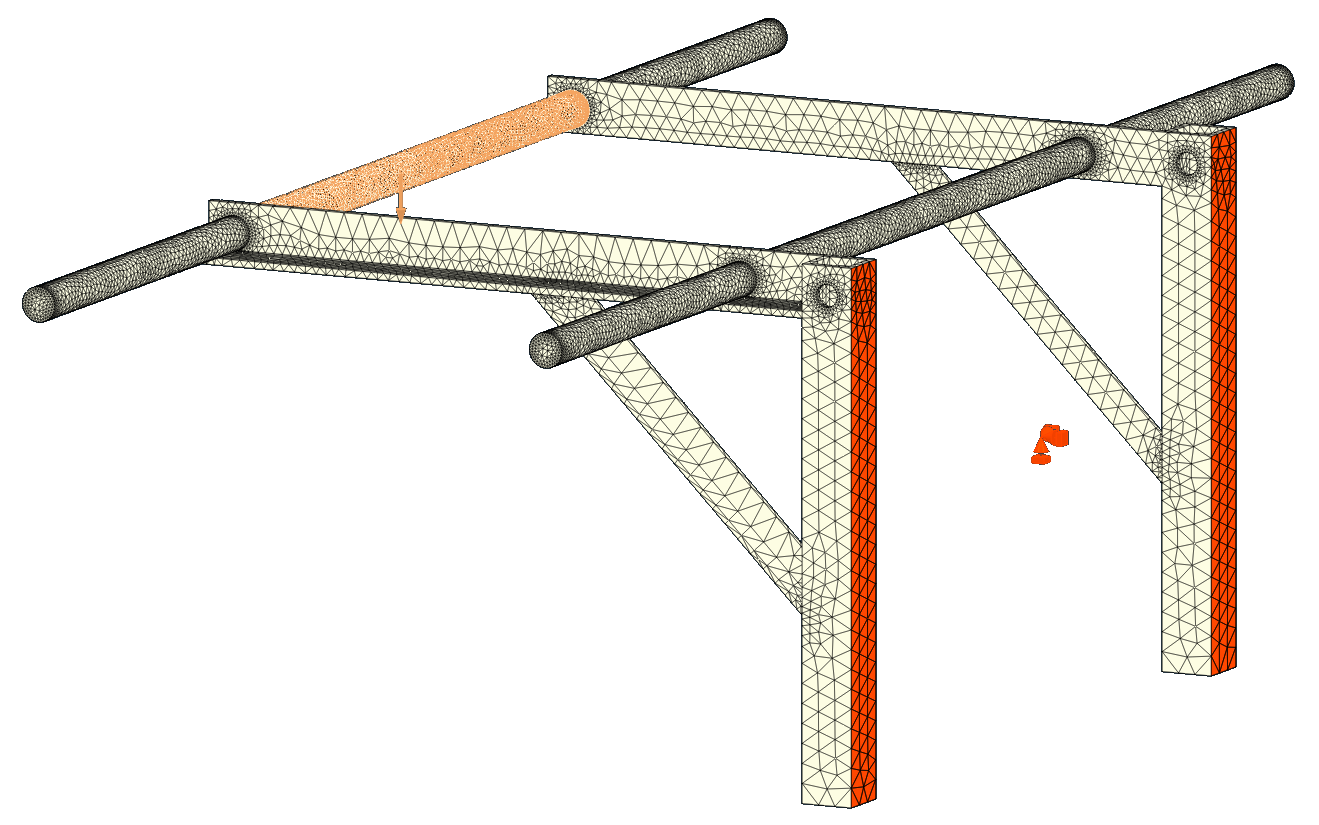
[Composition]
Name = CalculiX-Steel w/ S420
Description = Standard steel material for
              CalculiX sample calculations
Father = Metal
[Mechanical]
Density = 7900 kg/m^3
PoissonRatio = 0.28
YoungsModulus = 210000 MPa
YieldStress = 235 MPa
[Constraints and Boundary]
Force = 200 Kg / 1961.33 N
Load = Primary dowel
Boundary-Fixed = SHS
[Mesh and FEM]
Gen. method = GMESH
Max-element size = 50mm
Ele. type = C3D10 Parabolic Tetra.
Solver = Calculix-PaStix w/o Nlgeom
No. of elements = 63485
Nodes = 123414
[Thermal]
SpecificHeat = 590 J/kg/K
ThermalConductivity = 43 W/m/K
ThermalExpansionCoefficient = 0.000012 m/m/K
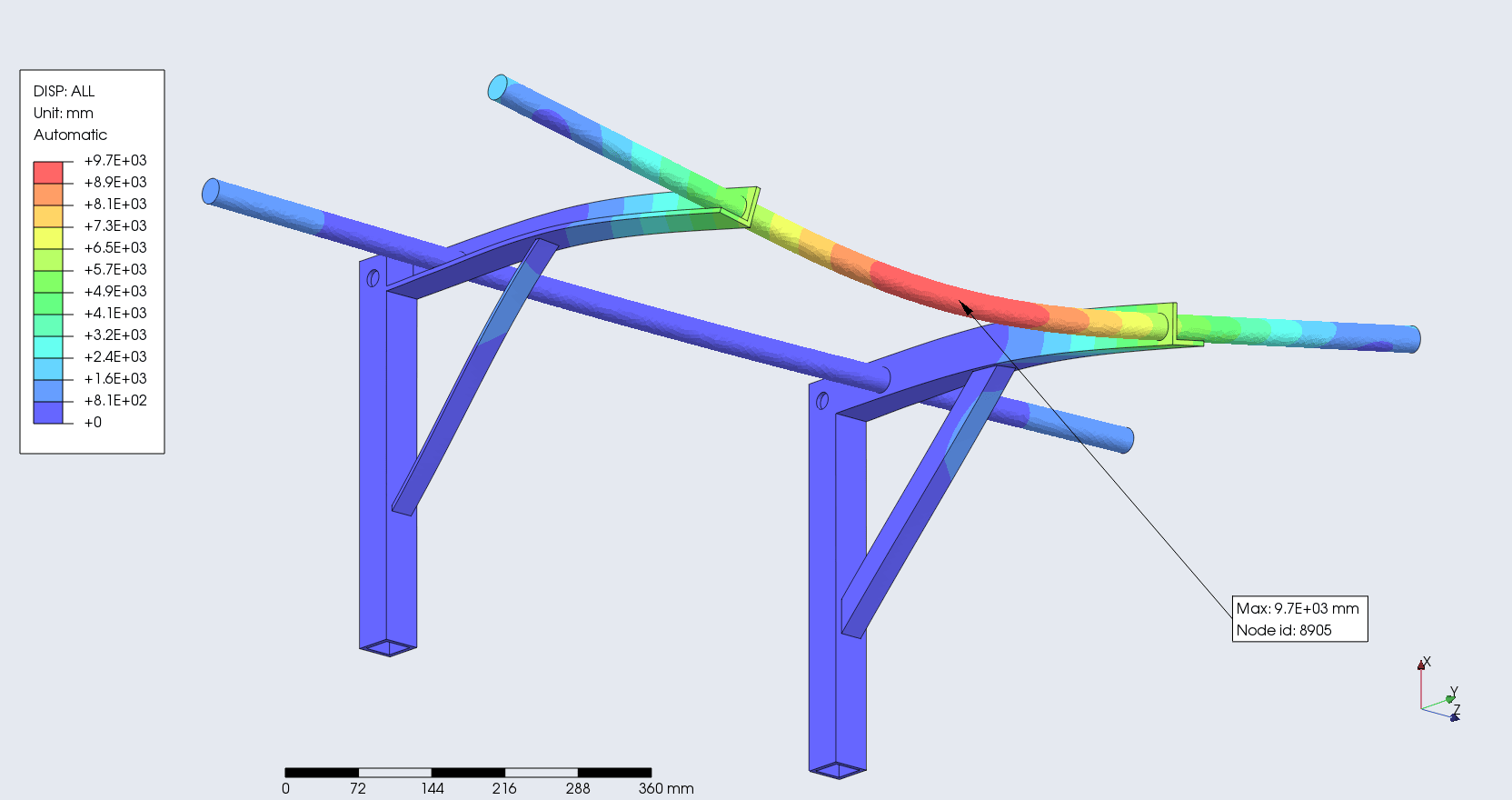
Displacement
Denotes the maximum movement/deflection during the load bearing process. Perdictably, it occured at the primary dowel where the load was exerted. For homogeniety, the dowel was assumed to be made of steel.
max-disp = 9.7E + 03 mm
max-u1 = 2E + 03 mm
max-u2 = 1.4E + 03 mm
max-u3 = 8.5E + 02 mm
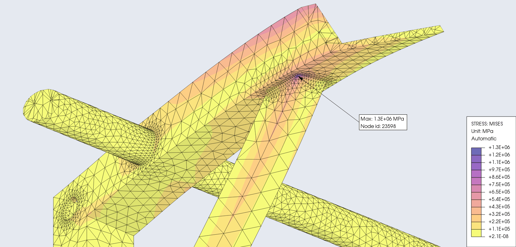
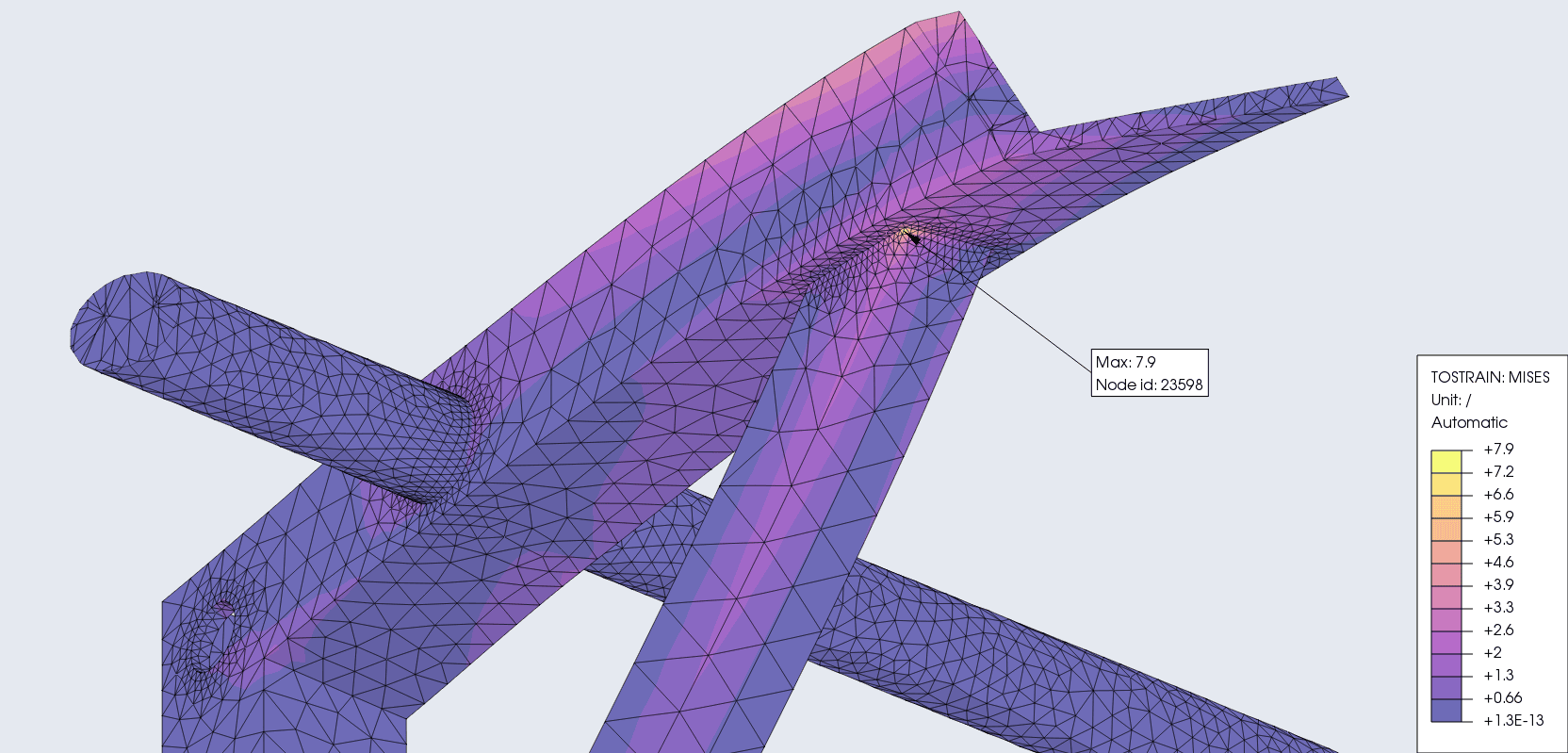
Von-Mises stress and strain
During the loading phase we obtain normal stress in X, Y, Z and shear stress in XY, XZ, YZ. The von Mises stress combines these 6 stress values to one value - an equivalent stress. It is always positive.
Mises-Stress = 1.3E + 06 MPa
Mises-Strain = 7.9
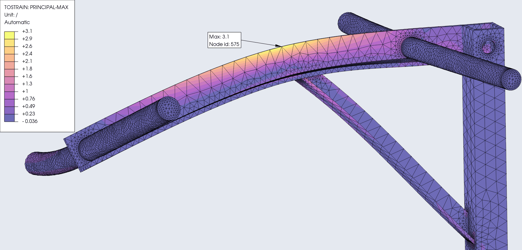
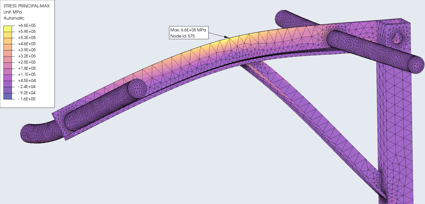
Max-principal stress and strain
The maximum principal stress and strain is a failure predictor that takes ductility of a material and outputs the fracture threshold.
Max-Stress = 6.6E + 05 MPa
Max-Strain = 3.1
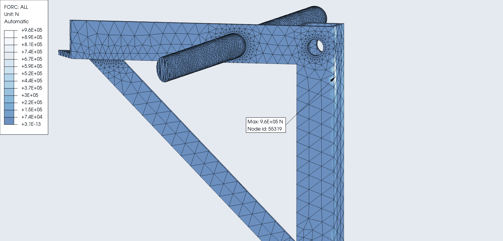
Reaction force
I like to think of this as more of a “pushing off” force. Here, its the reaction force on a body due to it pushing it self against an outside agent. Froce exerted by the anchor if you will.
Resultant = 9.6E + 0.5 N
This was more of a study of the design than the product because I cant imagine anything in the real-world having to exert 200kg of load on a pullup bar. In terms of the design, as long as dowels are homogeneous and fused to the body, L-beam collapsing or shearing was the primary point of failure. The force is spread well enough to make the threshold of failure very high. But it meant at full capacity it had a lot of potential energy. To prevent that build up, one could simply introduce a weaker dowel material to create a safer point of failure. As for my worry about the wall anchors shearing from the wall, we see from the R-FORC diagram (F3: normal to the wall) that the torque accentuated by the “L” shape of the body isnt too pronounced.
This was my first FEM study on a real-worls model. Being self-taught for now, I’m sure I have made some mistakes and wrong assumptions. So as I learn more, I will update this if there was some glaring foresight on my part.