Comp. Fluid Dynamics I
repository
This is the second installment in my unofficial series of Multiphysics Simulations. For this project, I compare the mechanisms of winged-lift and explore the results a CFD simulation on an origami paper airplane.
This differs from my last article concerning FEA in that this time I am analyzing the behavior of (solids) a fluid system. I’ve linked references at the end of the article. As always the mesh files and formatted calculations can be accessed from my Github page. Should you- the reader- find mistakes or conflict of sources, please feel free to create an issue there.
The tools I used, all of which are Open Source, are:
- FreeCad (CFDof addon)
- to construct the model using booleans on primitive solids and act as a GUI for OpenFoam and cfMesh
- cfMesh (
snappyHexMesh)- for stl to mesh/imp conversion and mesh coupling/refinement.
- BlueCFD-Core Project (OpenFoam port)
- a FOSS windows port of the CFD package from OPENFOAM
- Hisa (solver)
- a density-based compressible CFD solver for OF toolkit
- ParaView
- powerful powerful postprocessor to render results from Blue-CFD

The specs for our environment is given below:
[Constraints and Boundary]
Velocity = 5e+03 mm/s
Pressure = 0 Pa
Angle of attack = 5°
Sweep Angle = 70°
Inlet =
Subject =
Outlet =
Boundary-Wall = Slip (Inviscid)
[Physics Model]
Time = Steady
Flow = Single Phase
     = Incrompressible
     = Viscous
Turbulence = Laminar
Flow Field = Potential Flow
[ThermoDynamic Properties]
Fluid = Air
Temprature = 20°C
Pressure = 1 atm / 101325 Pa
Density = 1.2 kg/m^3s
Dynamic Viscosity = 1.8e-08 kg/mms
[Mesh refinement]
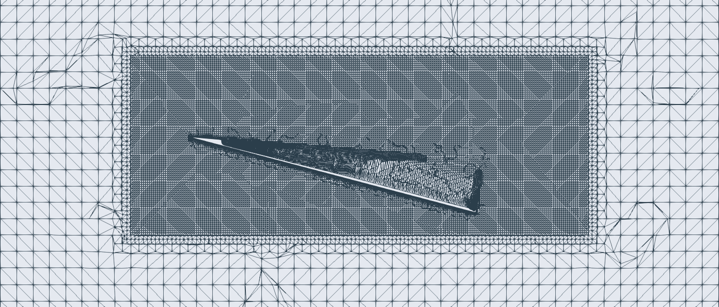
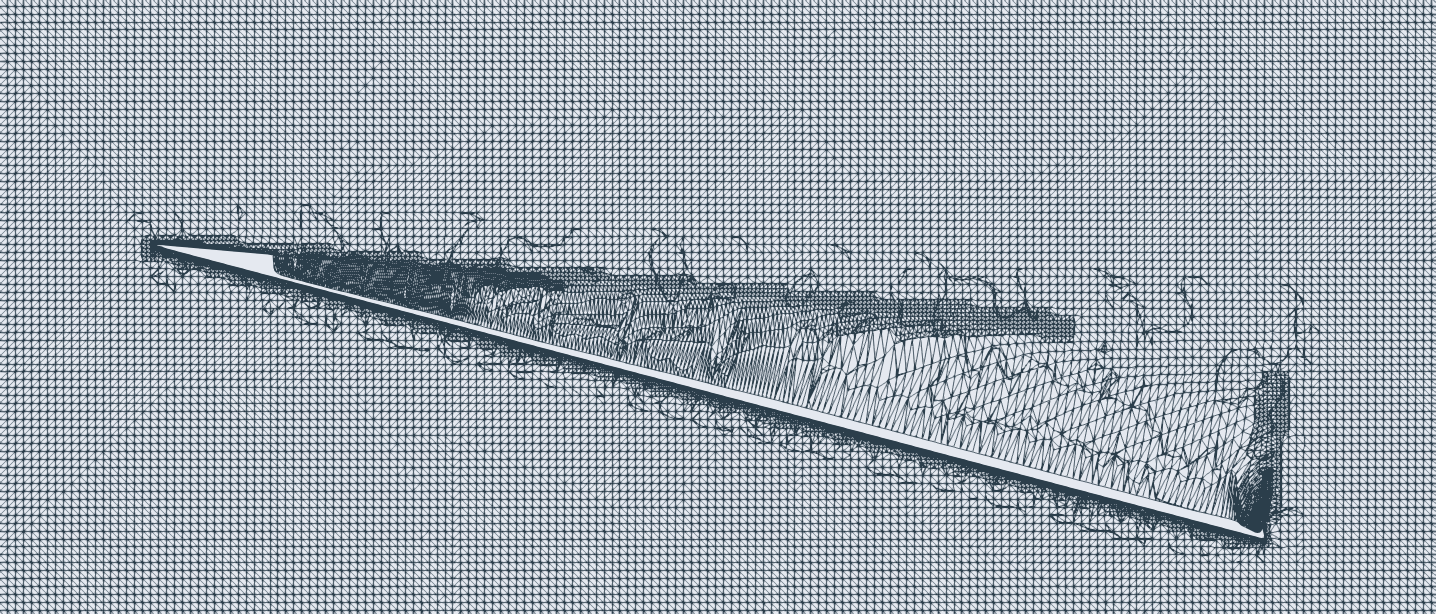
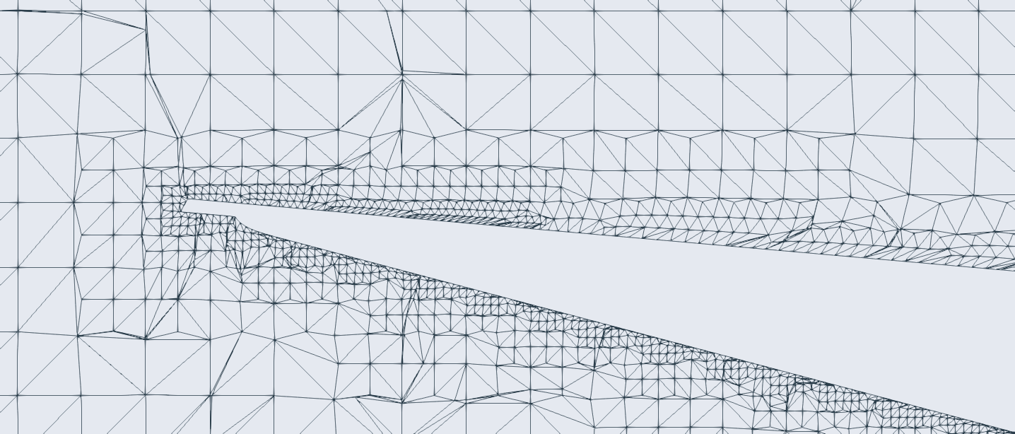
Gen. method = cfMESH
base-element size = 1.8mm

[Ref I]
relative element size = 0.040
surfaces = outer edges

[Ref II]
relative element size = 0.030
surfaces = nose

[Ref III]
relative element size = 0.198
volume = Cylinder002
An introduction.
I recently watched the behind the scenes of Red Bull’s Castle to Castle advert. Having watched an inverted stuntplane flying above the F1 car, it didnt occur to me until then that the Bernoulli’s principle of lift- where lift is dependent on the shape of an airfoil- is only really useful in the right orientation (up). But planes also have flaps that act like like rudders on a boat. Air being deflected by an angled surface has to produce a force. Does that mean there were two saperate forces in that inverted plane fighting eachother? And was the force given by the shape of the foil that much smaller than force given with Newton’s classic laws?
The debate of Bernoulli
In most text-books “faster air at top, slower at bottom” seems to be the go-to explanation for lift, with Newton’s laws being oddly missing. So I visited some aviation fourms only to find out “lift” itself didnt have a consensus explanation. Berneouli’s model of lift was especiailly polarizing as some argued it was statistically insignificant compared to Newton’s laws, some argued it was primitive, some said it was misleading and an extremely adamant minority argued that it and Newtonian model were one and the same. Intrigued by this controversy and my recent intrest in real-world simulations, I dived deeper into this topic with a project in my mind.
Clearing some of the smoke
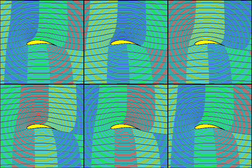
- “equal transit time” theory— “path at the top of the airfoil is curved, so to catch up to the air at the bottom, it has to travel faster”- is wrong. The fallacy here is that there is no physical reason that the two parcels of air must reach the trailing edge simultaneously and that’s what we observe in practice.
- A symmetric airfoil (like the ones in stunt planes) needs to have a positive angle of attack to produce lift.
- The Newtonian model of lift (momentum is not contradictory nor supplementary to Bernoulis principle. Those are two exactly equivalent mathematical formulations of the same physics.
- lift because air deflects down, that’s Newton.
- lift because of pressure/velocity difference between the two sides isn’t symmetric, that’s Bernoulli.
I can show that the sun exists by pointing at a shadow, by pointing at the reflection of the moon, or by pointing at the sun itself. That doesn’t mean that one of these explanations explains 50% of the sun, and the others do another part. They all point to 100% of the sun’s presence.
The humble paper airplane (CFD)
I am a big fan of John Collins, the paper airplane guy, and his book Fantastic Flight was a cherished posession from my childhood. This made my ignorance about the fundamental mechanisms of flight especially frustrating. To visualise the theory and train my intuition, I got some 3d models of paper airplanes from @demetr0s_designs designed a wind tunnel in a CFD environment.
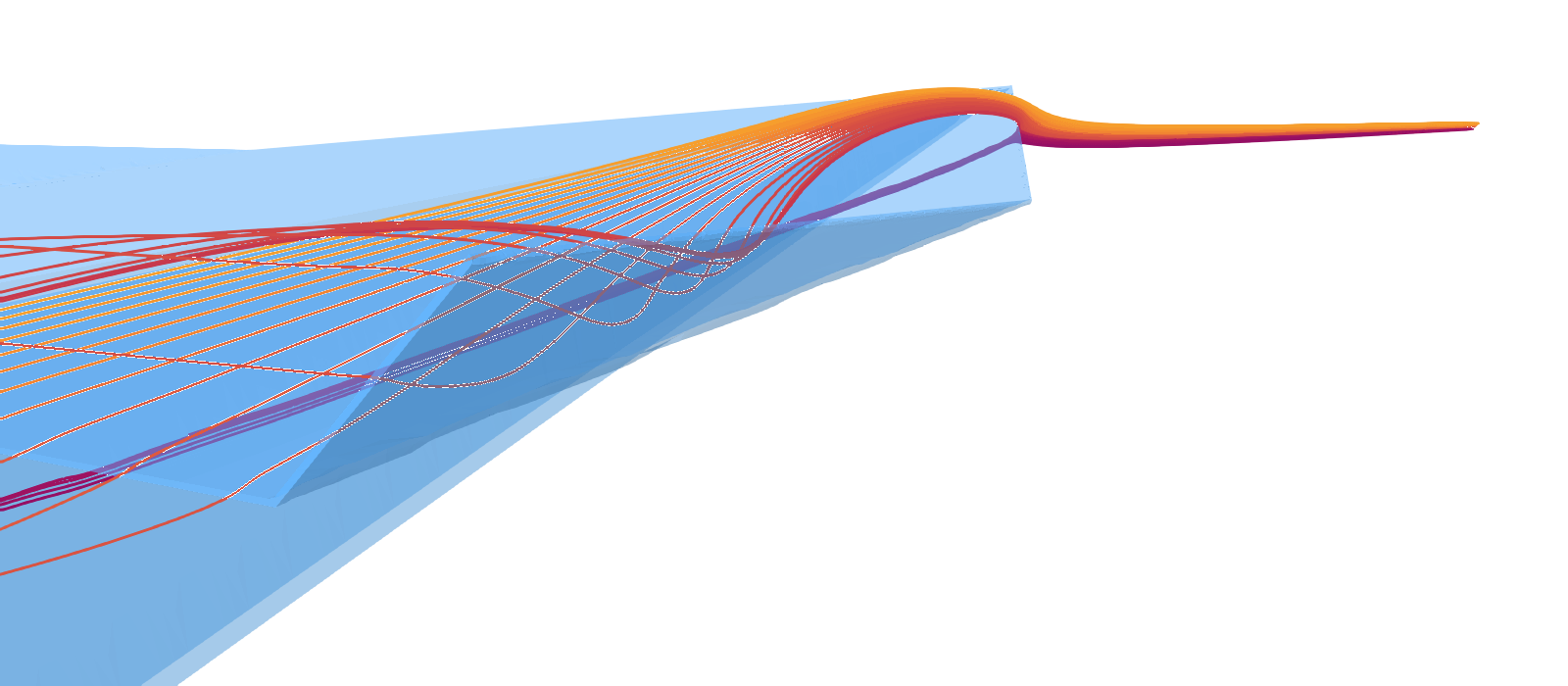
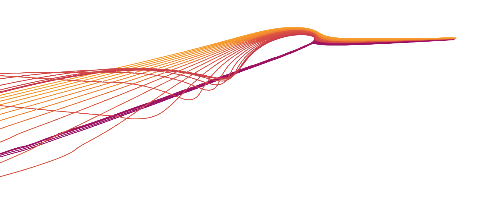
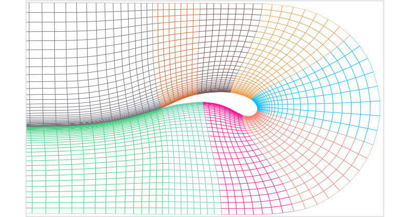
- How are paper airplanes different from airfoils?
The primary function of Airfoils or curved surfaces on a wing is to reduce drag. A resemblance of an airfoil shape can be seen in laminar streamers from the simulation of flat wings (unsubstantiated in references for now). Functionally, symmetrical airfoils are similar to flat wings as they both need a positive non-zero angle of attack.

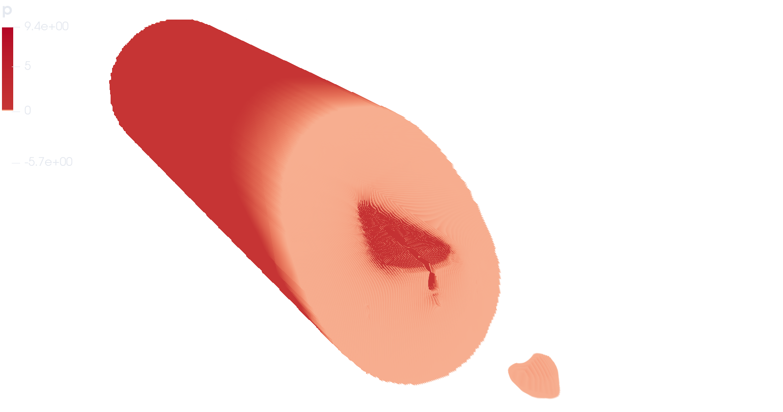
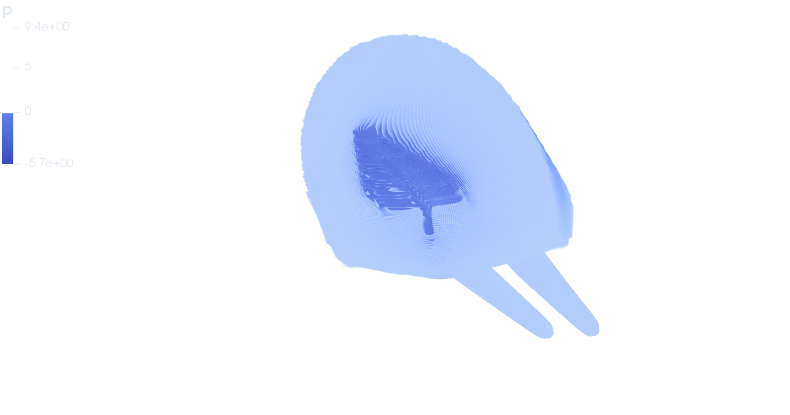
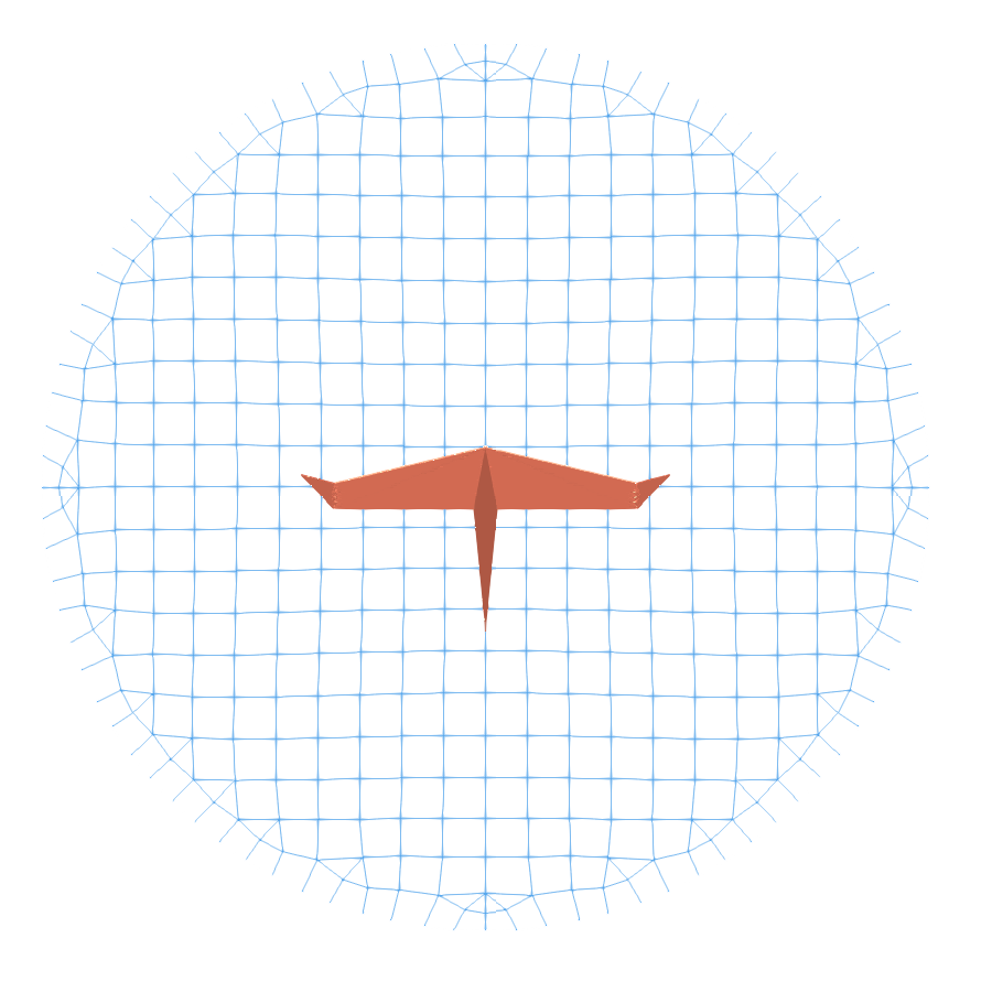
- Why does low pressure get built on top of the wing? It’s definitely not the curvature because this wing is flat..
Where assymetrical airfoils can create lift even if the AOA is parallel to the wind, flat wings and sym. airfoils cannot. So they have to maintain a positive non-zero AOA to generate lift. For a paper airplane, incoming air doesnot meet the plane’s crossection but rather the shape of the wake of said plane. With Newtonian model we can imagine the air molecules as bullets hitting the bottom of the plane and transferring their momentum to make lift while the bullets do not have a direct path to the top of the wing creating a partial vacuum.
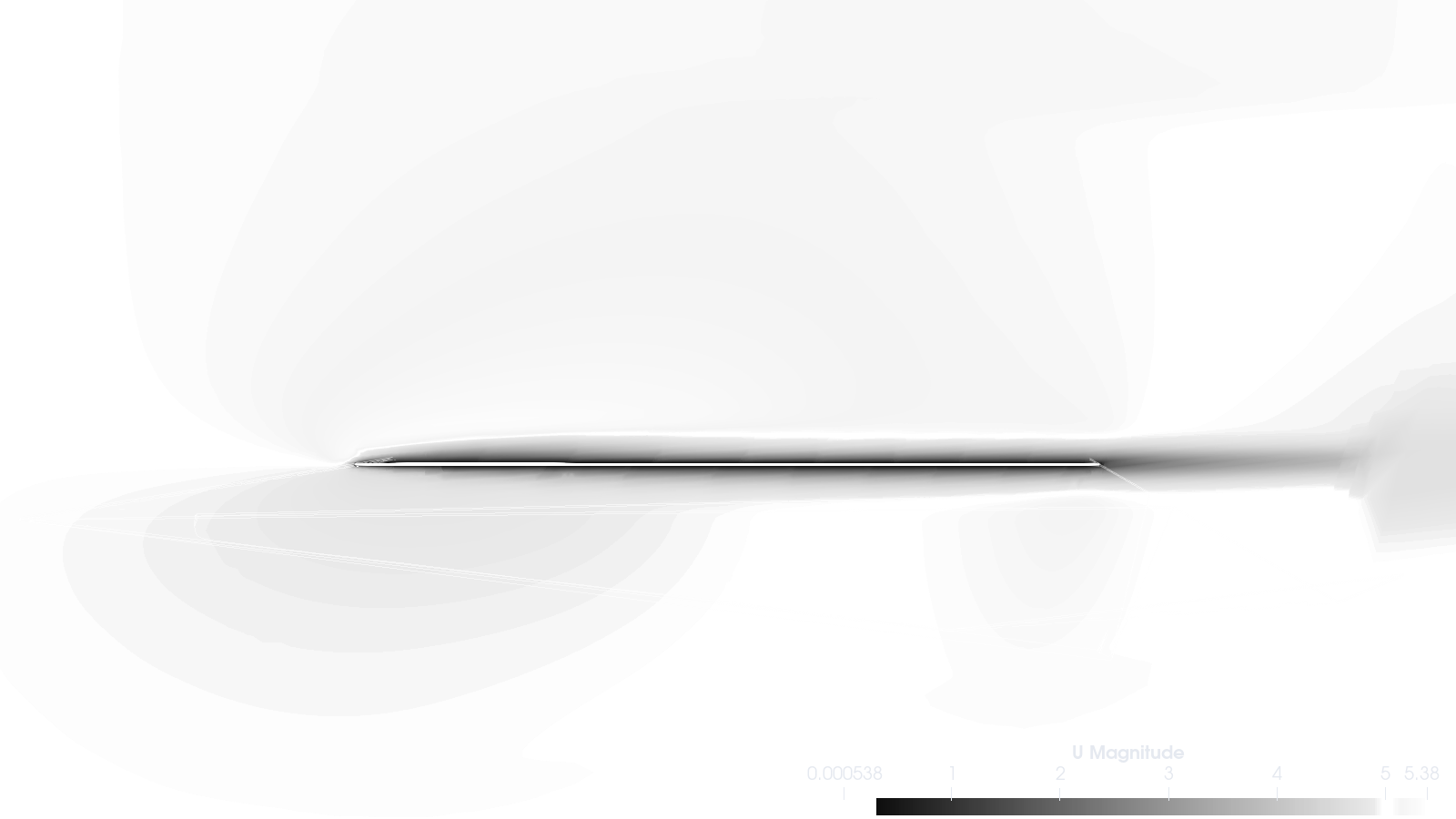
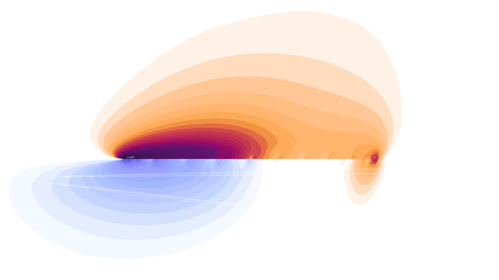
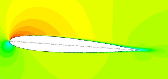
- Can the lift in a paper airplane be observed with Bernoulli’s model?
Every lift can, in some way or another, be visualised through Bernoulli’s model because it derives its equations from the laws of thermodynamics. For a paper plane, with the help of a virtual wind tunnel, we can observe that a flat, symmetrical wing will have asymmetrical airflow speed for a non-zero angle of attack.
Vortex lift and Wake turbulence
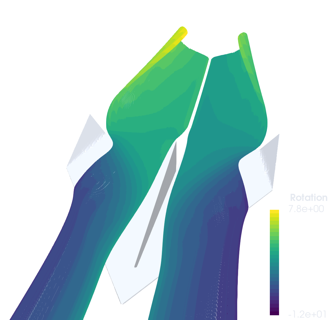
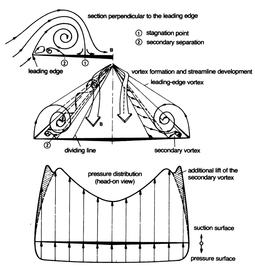
Winglets reduce a phenemona called wake turbulence. Out at the wing-tip (or leading edge for delta-wings), all the higher pressure air from the bottom of the wing is no longer blocked from rushing to the high pressure area above the wing by the wing itself and the air flows up around the tip/edge. This produces vortices that(generally) have an affect akin to increasing the viscosity of air, increasing the drag on an aircraft.
But for highly swept wings (>60°) at an high angle of attack, vorticies actually produce their own lift. I came across this helpful discussion in the aviation stackexchange about vortex lift. And while my plane’s AOA was not enough and winglets are detrimental to this effect, you can still see the initial stage of such vortices with the help of streamers or pressure contours.
The vortices form ‘vortex sheets’ along the wing. Air is sucked into the vortex sheets and accelerated downward. As the airspeed in the vortex is high, the pressure is low. This low pressure on the upper surface produces lift.
References
- “The Enigma of Aerodynamic Lift” in Scientific American 322, 2, 44-51
- Dash, Ankan. “CFD Analysis of Wind Turbine Airfoil at Various Angles of Attack.” (2016)
- See How It Flies (3.6) -John S. Denker
- Polhamus, Edward C.. “A concept of the vortex lift of sharp-edge delta wings based on a leading-edge-suction analogy.” (1966).
- Rütten, Markus & Karl, Sebastian & Lindermeir, Erwin. (2014). Numerical Investigation of Engine Exhaust Plume Characteristics of Unmanned Combat Air Vehicles. 32nd AIAA Applied Aerodynamics Conference. 10.2514/6.2014-2838.
- Paeres, David & Santiago, Jean & Lagares, Christian & Rivera, Wilson & Craig, Alan & Araya, Guillermo. (2021). Design of a Virtual Wind Tunnel for CFD Visualization. 10.2514/6.2021-1600.
- What is Vortex lift. Aviation Stackexchange